InternalsVisibleTo

Dear Future Jamie:

When you want to test private methods, do this:

1) Change the scope from private to internal

2) Add this attribute to the namespace of the class that has the private method:

[assembly: InternalsVisibleTo(“NameSpace.Class.Tests”)]

3) Add this using statement to the class that has #2 in it:

using System.Runtime.CompilerServices;


Love,

Past Jamie

Unit Testing and the Microframework

So I started writing some real code to handle the PWM signals coming into the Netduino from a RC receiver.  The simple code that I had has quickly  morphed into a jumbled mess of spaghetti code:

image

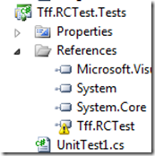
I stopped writing code and decided that this ripe for some unit testing.  I added a unit test project to my solution but I got this:

image

Sure enough:

image

This is the same problem I had with my Windows Phone app.  Instead of giving up on unit testing (which is what I did with my WP app, and now I am regretting it), I decided to take a separate approach.  I first thought of using a testable .dll that has the code for the Netduino app but I ran into the same problem:

image

So I need to create a test harness for my code in the Microframework.  Fortunately, when I googled that on bing, I found this great article.

Instead of adding a reference to the Microframework, I Added As Link to the class I want to test:

image

I can then test the methods in the class.

The problem with this way of testing is that if the class under test references other assemblies or services, those assemblies need to be referenced in the testing project.  What happened is that my testing project quickly became bloated and violated the Law Of Demeter.

I wonder if MSFT will come out with a testing framework for both the Microframework and/or the PCLs…

Capturing PWM with a Netduino (Part 2)

So I decided even if I can’t figure out what the signals are saying, at least I could capture the PWMs as they came into the Netduino.

Knowing that the PWM pulse occurs every 20MS, the duration of the pulse determines the direction of the servo.  For example, if the pulse is 2MS, the servo should move up.  If the pulse is 1MS the servo should move down.

The Netduino allows you to capture the leading edge of the pulse and the trailing edge of a pulse.  Theoretically. if you measure the leading edge of pulse 1 to the leading edge of pulse 2, the difference will always be 20MS.    However, the difference between the trailing edge of the pulse and the leading edge of the next pulse (or the trailing edge of the next pulse) will vary depending on the RC receiver’s signal.

That means I need a way to capture the 2 edges of the pulse, calculate the difference between them, and then do something with that information (altering a servio’s position for example).

My first approach was like this

public static void Main()
{

    InterruptPort inputPort = new InterruptPort(Pins.GPIO_PIN_D0,
        true, Port.ResistorMode.Disabled, Port.InterruptMode.InterruptEdgeBoth);

    inputPort.OnInterrupt += new NativeEventHandler(inputPort_OnInterrupt);

    Thread.Sleep(3000);
}

static long leadingEdge = 0;
static void inputPort_OnInterrupt(uint data1, uint data2, DateTime time)
{
    if (data2 == 1)
    {
        leadingEdge = time.Ticks;
    }
    else
    {
        long pulseWidth = (time.Ticks - leadingEdge)/1000;
        Debug.Print(pulseWidth.ToString());
    }
}

With the results like this:

image

I expected to see 20MS, not 14.  In any event, I then ran the same program and moved the stick up and down.  Sure enough, the pulse modulated.

image

However, it did not modulate in discrete values.  Rather, it rose and dropped as if it was analog.

I then added this code to evaluate the rise and fall of the PWM:


static OutputPort outputPort = new OutputPort(Pins.ONBOARD_LED, false);

public static void Main()
{
    InterruptPort inputPort = new InterruptPort(Pins.GPIO_PIN_D0,
        true, Port.ResistorMode.Disabled, Port.InterruptMode.InterruptEdgeBoth);

    inputPort.OnInterrupt += new NativeEventHandler(inputPort_OnInterrupt);

    Thread.Sleep(Timeout.Infinite);
}

static long leadingEdge = 0;
static long priorPulseWidth = 0;
static void inputPort_OnInterrupt(uint data1, uint data2, DateTime time)
{
    if (data2 == 1)
    {
        leadingEdge = time.Ticks;
    }
    else
    {
        long currentPulseWidth = (time.Ticks - leadingEdge) / 1000;
        long pulseWidthChange = currentPulseWidth-priorPulseWidth;
        if(pulseWidthChange > 0)
        {
            outputPort.Write(true);
        }
        if(pulseWidthChange < 0)
        {
            outputPort.Write(false);
        }

        priorPulseWidth = currentPulseWidth;
    }
}

Sure enough, the LED went on when I pushed the stick up and turned off when I pulled the stick down – mostly.  I think that I need to smooth out the calculation so that I don’t capture each pulse – perhaps every 5th pulse. 

But the behavior is sporadic.  When I pull the stick down and leave it there, the LED sometimes blinks on and off.  Then it hit me as I was writing this – the reason why is that once the stick says still, the pulse still fires and the value is greater than the value when I was pulling the stick down.  Also, when the stick gets “pinned” to either Max up or down, the LED blinks rapidly.  I need to investigate that more.


So I then hooked up 4 digital outputs to represent the up/down of the throttle and the left/right of the turn. 

image

I then added the following code to set up the 2 inputs and the 4 outputs:

static OutputPort _forwardPort = new OutputPort(Pins.GPIO_PIN_D8, false);
static OutputPort _backwardsPort = new OutputPort(Pins.GPIO_PIN_D9, false);

static OutputPort _leftPort = new OutputPort(Pins.GPIO_PIN_D10, false);
static OutputPort _rightPort = new OutputPort(Pins.GPIO_PIN_D11, false);

public static void Main()
{
    InterruptPort leftStickPort = new InterruptPort(Pins.GPIO_PIN_D0,
        true, Port.ResistorMode.Disabled, Port.InterruptMode.InterruptEdgeBoth);
    leftStickPort.OnInterrupt += new NativeEventHandler(leftStickPort_OnInterrupt);

    InterruptPort rightStickPort = new InterruptPort(Pins.GPIO_PIN_D1,
        true, Port.ResistorMode.Disabled, Port.InterruptMode.InterruptEdgeBoth);
    rightStickPort.OnInterrupt += new NativeEventHandler(rightStickPort_OnInterrupt);

    Thread.Sleep(Timeout.Infinite);
}

I then added the following code for the left stick:

static long rightStickLeadingEdge = 0;
static void rightStickPort_OnInterrupt(uint data1, uint data2, DateTime time)
{
    if (data2 == 1)
    {
        rightStickLeadingEdge = time.Ticks;
    }
    else
    {
        long currentPulseWidth = (time.Ticks - rightStickLeadingEdge) / 1000;

        switch (currentPulseWidth)
        {
            case 18:
                {
                    _forwardPort.Write(true);
                    _backwardsPort.Write(false);
                    break;
                }
            case 17:
                {
                    _forwardPort.Write(true);
                    _backwardsPort.Write(false);
                    break;
                }
            case 16:
                {
                    _forwardPort.Write(true);
                    _backwardsPort.Write(false);
                    break;
                }
            case 15:
                {
                    _forwardPort.Write(true);
                    _backwardsPort.Write(false);
                    break;
                }
            case 14:
                {
                    _forwardPort.Write(false);
                    _backwardsPort.Write(false);
                    break;
                }
            case 13:
                {
                    _forwardPort.Write(false);
                    _backwardsPort.Write(true);
                    break;
                }
            case 12:
                {
                    _forwardPort.Write(false);
                    _backwardsPort.Write(true);
                    break;
                }
            case 11:
                {
                    _forwardPort.Write(false);
                    _backwardsPort.Write(true);
                    break;
                }
            default:
                {
                    _forwardPort.Write(false);
                    _backwardsPort.Write(false);
                    break;
                }
        }
    }
}

Sure enough, moving the stick and down saw the expected response from the LEDs.  I went to test the right/left stick

and that also acted as expected.  I then hooked up a relay module to the output and used a higher-voltage power source (the relay can go up to 250) and a small light.  Here is the final rig (note that I am using the Netduino 5.0V for the power source of the RC receiver):

image

Sure enough, I can now control standard household electrical currents using a RC transmitter and receiver.

Capturing PWM on a Netduino

I have been trying to send signals to my Netduino from a R/C transmitter and capture and analyze those signals.  To that end, I have a Spektrum AR600 RC transmitter and receiver.  My first stop was the Netduino forms where there was one very helpful person named Hanzibal who answered my questions.  I also had to use this great article that explains how PWM works in an RC unit.

Basically, the RC receiver sends a pulse of electricity every 20 MS.  This pulse will one of three lengths: 1 millisecond, 1.5 millisecond, or 2 milliseconds.  As I understand the article, 1.5 milliseconds means that servo should stay in the same position it is currently in (do nothing), 1 millisecond means that it should move down a given number of degrees and 2 milliseconds means that the servo goes up a given number of degrees.  The servo itself determines the turn rate and if the servo is at its max, it will ignore the signal.

My first challenge is to set up my hardware that will:

  1. 1) not destroy the hardware I am using
  2. 2) capture the PWMs

Thanks for Hanizbal and some significant trial and error, I set up my Netduino like so:

image

You will notice that the RC receiver is powered by a 4.8 V battery pack versus the 3.3V or 5.0V output of the Netduino.

Some of the things I learned are:

You don’t need a ground from the RC receiver to the Netduino board.  The only wire you need to connect is the Signal wire from the RC receiver to the Digital I/O port.

This is not completely fool-proof.  Sometimes when I deploy with the RC receiver connected to the board, I get this:

imageimage

I found that unplugging the Netduino cord and plugged it back into the Netduino, the code published.

With this in mind, I jumped into Visual Studio fired up a Netduino project.  I first looked at the PWM class

   image

The problem is that the PWM class does not have a GetPulse method or EventHandler.  This is a limitation that is not present in the Arduino as documented in this post.

I then looked at the Interrupt Port class like this person did.  I created some code like this:

public static void Main()
{

    InterruptPort inputPort = new InterruptPort(Pins.GPIO_PIN_D0,
        true, Port.ResistorMode.Disabled, Port.InterruptMode.InterruptEdgeBoth);

    inputPort.OnInterrupt += new NativeEventHandler(inputPort_OnInterrupt);

    Thread.Sleep(3000);
}

static void inputPort_OnInterrupt(uint data1, uint data2, DateTime time)
{
    Debug.Print(data2 + ":" + time.Millisecond + ":" + time.Ticks);
}

When I ran it with the RC receiver unplugged I got this:

Done.

Waiting for debug commands…

The thread ‘<No Name>’ (0x1) has exited with code 0 (0x0).

So the port was not receiving any signals or generating any kind of false signal.

When the RC receiver was plugged into the port, I got:

1:273:128752416062731306

0:274:128752416062743466

1:295:128752416062957226

0:296:128752416062969386

1:318:128752416063183360

0:319:128752416063195520

1:340:128752416063409280

0:342:128752416063421653

1:363:128752416063635413

0:364:128752416063647573

1:386:128752416063861333

0:387:128752416063873706

1:408:128752416064087466

I then fiddled around with the InterruptMode and this is what I found:

  • InterruptEdgeLow= 0
  • InterruptEdgeLevelLow= None
  • InterruptEdgeHigh= 1
  • InterruptEdgeLevelHigh= None
  • InterruptEdge=Both 1 && 0
  • InterruptNone= Exception

So looking at the values of the interrupts, I can’t use time.Milliseconds because it is an Int32 – it doesn’t have the level of precision to read 1.5 MS.

I then took this dataset and calculated the difference in ticks between the 0 and the 1 for each group:

image

With 10,000 ticks in a millisecond, it means the neutral pulse is 1.2 MS, not 1.5 MS as I initially thought.

This looks promising because at least it appears to be consistent

The battery pack supplying the 4.8V to the RC receiver then died.  I disconnected the battery pack and plugged the receiver into the Netduino 5V output and ran the same experiment again:

image

So the Period Length depends on the amount voltage coming in.  Also, it the difference is no longer consistent.

I decided to run 1 more experiment – push the stick up and down with the 5V power source:

image


Sure enough, The PW does change.  The range is from 1.0016 to  2.  The problem is that there is a wide range of possible values for the Pulse Width:

image

I was expecting only 3 values.  This is showing values 1.0, 1.1, 1.2, etc…  Without a discrete value, there is no way of determining if the stick is going up or down – unless perhaps I can determine that anything under 1.5 is down and above is up?  More hacking is in order…

Dependency Injection: Keeping It Simple

When I gave my talk at TriNug’s SIG about the SOLID principles, I whipped up an example of Dependency Injection (DI) that some people really liked.  I decided to blog about it.  Consider a basic console application that has a single Interface included – Animal.  The Animal interface looks like this:

public interface IAnimal
{
    void Talk();
    void Eat();
}

The Console application includes a couple of classes that implement the interface:

public class Elephant: IAnimal
{
    public void Talk()
    {
        Console.WriteLine("Trumpet");
    }

    public void Eat()
    {
        Console.WriteLine("Yummy Peanuts");
    }
}

public class Seal(): IAnimal 
{
    public void Talk()
    {
        Console.WriteLine("Ark Ark");
    }

    public void Eat()
    {
        Console.WriteLine("Yummy Fish");
    }
}

Then in the Main method, I want to inject in an animal at run time.  I could write something like this:

static void Main(string[] args)
{
    IAnimal animal = ????;
    animal.Talk();
    animal.Eat();
}

What I don’t want to do is to have a switch/if..then statement in the Main function because as new animals are added to my project, I would have to update existing code and violate the Open/Closed principle.  I know if a couple of ways around this problem:

  • Using a Dependency Injection Framework like Unity
  • Using Microsoft Extension Framework
  • Use a Factory Pattern
  • Injecting the name of the class and using Activator to resolve. Note that this name can come from a database call or a .config file.

A DI framework seems a bit too heavy for this kind of solution.  I tried MEF and quickly gave up, Using a factory pattern delays but does not alter the problem resolution.  I think the Activator keyword is the best solution to my problem.

To that end, I added a section in my .config file like this:

<configuration>
  <appSettings>
    <add key="animalTypeName" value="Tff.PoorMansDependencyInjection.Seal"/>
  </appSettings>
</configuration>

And then in my Main method:

String animalTypeName = ConfigurationManager.AppSettings["animalTypeName"].ToString();
Type animalType = Type.GetType(animalTypeName);
IAnimal animal = (IAnimal)Activator.CreateInstance(animalType);
animal.Talk();
animal.Eat();
Console.ReadKey();

And I get this:

image

HTML5 && MCSD

I was interested in keeping up my certifications with Microsoft and I am at a decision point.  I went to their new MCSD website here and cam to a decision point.  I could either get a MCSC in Web Applications using HTML5 or get a MCSD for Windows Store apps using C# and XAML.  Not sure what to pick, I hit Dice:

image

or

image

So I started with this:

image


and in their  1st java script example:

<!DOCTYPE html>
<html>
<head>
    <title>This is a test</title>
</head>
<body>
    <script>
        var drink = "Energy Drink";
        var lyrics = "";
        var cans = 99;

        while (cans > 0) {
            lyrics = lyrics + cans + " cans of " + drink + " on the wall <br>";
            lyrics = lyrics + cans + "cans of " + drink + "<br>";
            lyrics = lyrics + "Take one down, pass it around,<br>";

            if (cans > 1) {
                lyrics = lyrics + (cans - 1) + " cans of " + drink + " on the wall <br>";
            }
            else {
                lyrics = lyrics + "No more cans of " + drink + " on the wall <br>";
            }
            cans = cans - 1;
        }

        document.write(lyrics);
    </script>
</body>
</html>

I got

image

So I hit up NuGet and I found:

image


That still didn’t do the trick so I went to this site and realized I had to point my browser to HTML5

image

But that still didn’t work.  I can get it to work in VS2010 like this:

<script type="text/javascript">

image

But I want to remove the script type

So I hit up Twitter – still no luck.  I gave up.  I will have to chalk it up to VS2010 quirkiness.